
Article 690.47: Grounding Electrode System


This Article is extracted from Mike Holt’s Illustrated Guide to Understanding NEC® Requirements for Solar Photovoltaic Systems.


Understanding NEC Requirements for Solar Photovoltaic Systems, Based on the 2011 NEC


Click here to buy a copy or read more about it.   


*Please note in the follwing extraction that blue underlined text indicates a 2014 NEC change.


Section 690.47 – Grounding Electrode System

(A) Alternating-Current PV System Grounding Requirements. For ac PV systems, a grounding electrode system must be provided in accordance with 250.50 through 250.60, with the ac grounding electrode conductor installed in accordance with 250.64.Figure 690–109

Im,age


Figure 690–109

(B) Direct-Current PV System Grounding Requirements. For dc PV systems, a grounding electrode system in accordance with 250.166 for grounded systems, or 250.169 for ungrounded systems, must be provided. Figure 690–110

Image3

Figure 690–110

A common dc grounding-electrode conductor can service multiple inverters. Section 250.166 is used to size the common grounding electrode and the tap conductors. The tap conductors must be connected to the common grounding-electrode conductor by exothermic welding or with connectors listed as grounding and bonding equipment.

The ac grounding electrode system can be used for equipment grounding of inverters and for the ground-fault detection reference for un-grounded PV systems.

(C) PV Grounded System with Alternating-Current Power System. Grounded PV systems constructed of dc modules must have the dc system grounded by one of the following methods:

(1) Separate dc Electrode. A grounding electrode conductor run from the marked dc GEC point at the inverter to the separate dc grounding electrode sized no smaller than the largest ungrounded dc conductor, but no smaller than 8 AWG [250.166(B)]. The dc grounding electrode must be bonded to the ac grounding electrode with a bonding jumper sized to the larger of the dc grounding electrode conductor [250.166] or ac grounding electrode conductor [250.66]. Figure 690–111

Image4

Figure 690–111

(2) Alternating-Current Grounding Electrode. A grounding electrode conductor sized in accordance with 250.166 must be run from the marked dc GEC point at the inverter to the ac grounding electrode. Figure 690–112

Image3

Figure 690–112

Where an ac grounding electrode isn’t accessible, the dc grounding electrode conductor must terminate to the ac grounding electrode conductor with a connector listed as grounding and bonding equipment. 690–113

Image2

Figure 690–113

(3) Combination ac Equipment Grounding Conductor/dc Grounding Electrode Conductor. For grounded PV Systems, the ac equipment grounding conductor sized to the larger of 250.122 or 250.166 can serve as both the ac circuit equipment grounding conductor and dc grounding electrode conductor. Figure 690–114
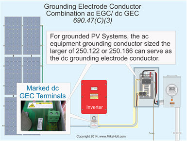
Image3

Figure 690–114

Author’s Comment:
  •  The ac equipment grounding conductor is sized in accordance with 250.122 based on the rating of the ac circuit overcurrent protection device; the dc grounding electrode conductor is sized no smaller than 8 AWG and no smaller than the dc circuit conductors [250.166(B)].

Question: What size EGC/GEC is required for a grounded PV system, where the inverter dc input circuit conductors are 14 AWG and the inverter ac output circuit conductors are 10 AWG protected by a 30A breaker? Figure 690–115

Answer: Table 250.122 requires the ac EGC to be sized no smaller than 10 AWG, and 250.166(B) requires the dc grounding electrode conductor to be no smaller than the largest dc circuit conductors, but no smaller than 8 AWG. In this case, the combined EGC/GEC must be no smaller than 8 AWG.
Image3

Figure 690–115

For ungrounded systems, the ac equipment grounding conductor sized no smaller than required by 250.122 based on the rating of the ac circuit overcurrent protection device can serve as both the ac circuit equipment grounding conductor and dc grounding electrode conductor.Figure 690–116
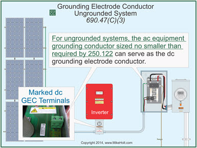
Image3

Figure 690–116

(D) Auxiliary Electrode for Array. A dc grounding electrode conductor from the array structure sized in accordance with 250.166 must be connected to a grounding electrode that complies with 250.52 and 250.54.

The metal structure of a ground- or pole-mounted PV array can serve as the grounding electrode if it complies with 250.52.

Roof-mounted PV arrays can use the metal frame of a building or structure as the electrode if it meets 250.52(A)(2). Figure 690–117

Image3

Figure 690–117

Ex No. 1: An array grounding electrode(s) isn’t required where the load served by the array is integral with the array.
Ex No. 2: An additional array grounding electrode(s) isn’t required if located within 6 ft of the premises wiring electrode.
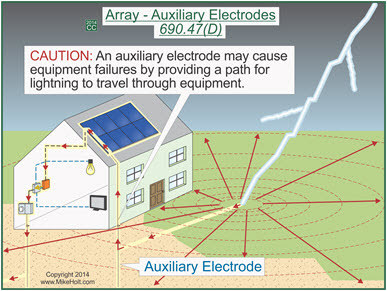
Author’s Comment:
  • Auxiliary electrodes have no NEC requirements since they serve no useful purpose relating to electrical safety, yet are permitted. If an auxiliary electrode is installed, it isn’t required to be bonded to the building grounding electrode system, required to have the grounding conductor sized to 250.66, or to comply with the 25-ohm requirement of 250.53(A)(2) Ex [250.54].

CAUTION: An auxiliary electrode typically serves no useful purpose, and in some cases it may actually cause equipment failures by providing a path for lightning to travel through electronic equipment. Figure 690–118

Image3

Figure 690–118

2014 Change Analysis: The requirements for grounding the PV array were included in the 2008 Code, but disappeared in the 2011 edition. Due to the fact that there was no technical substantiation in either the report on proposals or the report on comments to remove it from the 2011 edition, it was inserted back into the 2014 Code without substantiation.


This Article is extracted from Mike Holt’s Illustrated Guide to Understanding NEC® Requirements for Solar Photovoltaic Systems based on the 2014 NEC®. 


Understanding NEC Requirements for Solar Photovoltaic Systems, Based on the 2011 NEC

Comments

Popular posts from this blog

NEC Code Test Prep 2020 Update & Free Download

Welcome to the year 2020!  Well, for us in TX we are still in the year 2017. That means that if you are going to take your electrical exam, you will be testing out of the 2017 NEC code book. TDLR is adopting the 2020 NEC code by September 1st.  As of September 1st, the PSI exam for the electrical license will be based on that code. You can take your exam now until August under the 2017 code but after that, you will need to update to the new code. If you have already been approved to take the exam, you should really get on the ball and start studying now. 3 Routes to prepare for the NEC Code Test Prep Consider these options for preparing for the electrical exam.  What route you take depends on how you retain information best, your budget and your time frame. If you are in the Texas area and have at least a month to study, come to the 2 day seminar.  This seminar is specifically for the Texas electrical exam.  This NEC code test prep course ...

Texas PSI Exam - Important Articles of the Code Book Ch 2

Get to know chapter two for the Texas PSI test. This excerpt is from our article at ElectricalExcel.com .  This material is presented in the Texas PSI Exam Prep Seminars.  Click here to learn more about the seminars. Texas PSI Exam Prep - Chapter 2 Review There are some sections of chapter two that you will see in the exam.  You’ll also have some smaller sections that we are not going to focus on today since they account for less than two questions out of 100. You’ll see these in the test, so write this down. Here are the most important Articles in Chapter 2: *210...Branch Circuit Rules & Requirements. - You'll also find the rules for GFCI installation, your arc fault rules and requirements. *215...Feeders.  *220...Calculations . - This article is specific calculations. The test is very heavy on article 220. You've got to know article 220 very well.  In the seminar we go through it a lot.  You’ll leave the seminar with 220 oozing out of your ears....

7 Tips to Pass the PSI Test in Texas | Electrical Exam Prep

Here are some prep tips you can look over this week.  Please take a moment to look over the material on our website.  Let us know if there is anything you want us to cover! For in-depth material, check out our seminars in Texas .  Classes are extra small to comply with COVID-19, so register fast to hold your seat. Tip #1  The test is based on the current NEC. 🚩Allowed: -to bring a standard printed NEC (not a hard-cover) -small notes written in pen -to tab your book with NEC tabs 🚩Not Allowed: -Hardcover NEC -Small printed items tucked in the book, -Stapled items to any pages in the book, -large paragraphs of information or calculations in the book. Tip #2 Questions in the Exam When you go take the exam, one of the first objectives is to scan the test for all time wasting questions designed to confuse you. Tip #3 Don’t Freak Out When you are sitting in for the electrical test you will see other people walking out of the test room sooner than...